
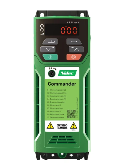
Why Won't My VFD Start the Motor?
A VFD that powers up but refuses to start the motor can point to anything from a simple permissive signal problem to a serious internal drive fault. The fastest path is to avoid random resets and instead move through the system in order: display status, external wiring, power quality, control logic, motor/load condition, then internal drive components. This guide walks through practical VFD troubleshooting steps for engineers, technicians, and plant operators dealing with start-up problems in industrial or commercial motor control systems.
Why won’t my VFD start the motor?
A VFD won’t start the motor when one or more required start conditions are missing, blocked, or outside the drive’s protection limits. The issue may be external, such as no run command, an open safety interlock, loose wiring, incorrect input power, or a PLC communication fault. It may also be internal, such as overcurrent protection, high DC bus voltage, capacitor failure, a rectifier problem, or damaged power semiconductors.
The key is to treat “vfd not working” as a symptom, not a diagnosis. A Variable Frequency Drive is not just an on/off switch; it converts incoming AC power through a rectifier, stores energy on a DC bus, then uses an inverter section and control unit to create controlled output to the motor. If any part of that chain is unhealthy, or if the control system tells the drive not to run, you can end up with a motor not starting even though the display is lit.
Before repeated start attempts, pause and collect evidence. Repeatedly commanding a failed drive to run can stress the motor, load, and VFD. Good VFD diagnostics begin with what the drive is already telling you.
Start with the status display, not the toolbox
Most VFDs provide a fault code, warning, ready/not-ready status, run command status, reference speed, output frequency, output current, DC bus voltage, and input/output terminal states. These values help separate control problems from power problems. If the drive says it is “ready” but never receives a run command, you are looking at a control issue. If it receives the run command and trips immediately, you may be dealing with current, voltage, motor, load, or internal VFD issues.
Use the display to answer a few basic questions before opening panels:
-
Is the drive in fault, alarm, local, remote, ready, inhibited, or run state? A drive in the wrong control mode may ignore commands from the keypad, terminals, or PLC.
-
Is a start command actually present? If not, check pushbuttons, selector switches, PLC outputs, network commands, and safety relays.
-
Is the speed reference valid? A run command with a zero-speed reference may look like a failed start.
-
Does the drive trip instantly or after acceleration begins? Instant trips often point to short circuits, severe overcurrent, incorrect wiring, or internal faults. Trips during ramp-up can involve load torque, acceleration time, motor data, or mechanical binding.
-
What fault code appears first? The first fault is usually more useful than secondary faults that appear after repeated resets.
If you are trying to troubleshoot VFD behavior in a busy plant, document the exact message before clearing it. A single fault code can save hours of guesswork.
Common causes of VFD start-up problems
Many VFD won’t start the motor solutions begin outside the drive. External problems are common, easier to test, and often less expensive to correct than internal component failures.
Missing run permissive or control command
A VFD may be healthy but intentionally blocked from starting. Safety circuits, emergency stops, pressure switches, flow switches, overload contacts, door interlocks, remote/local selection, or PLC logic can all prevent operation. In networked systems, a communication fault can also stop the drive from receiving a valid run command.
Check the terminal status screen or input LEDs if available. Confirm that the run input changes state when commanded, that stop inputs are in the required state, and that the drive is set to accept commands from the intended source. Many start motor problems come down to local/remote mode mismatch after maintenance.
Incorrect or unstable incoming power
The VFD needs proper input voltage before it can create a stable DC bus and output waveform. Measure incoming power phase-to-phase and compare it with the drive nameplate and application requirements. As a practical check, incoming voltage should typically be within about ±5% of the expected value unless the manufacturer specifies otherwise.
Look for blown fuses, open disconnects, phase loss, undervoltage, overvoltage, loose lugs, or heat-damaged terminals. Loose power connections may cause arcing and voltage drop that only appears under load. If the display flickers, resets, or shows undervoltage during a start command, the supply side deserves close attention.
Wiring, grounding, and motor lead problems
Loose output leads, incorrect motor wiring, insulation breakdown, damaged conduit, moisture in junction boxes, or a grounded phase can stop a motor before it turns. Verify that motor leads are landed correctly and tightened to the specified torque. If the motor was recently replaced, confirm that the motor voltage and connection match the VFD output configuration.
Do not use a standard megohmmeter on a connected VFD output unless the drive is isolated according to the manufacturer’s instructions. Insulation testing can be useful, but only when performed safely and correctly.
Motor or load problems
A drive can trip because the motor or driven equipment is not free to accelerate. Pumps may be deadheaded or mechanically jammed. Fans may have seized bearings or blocked dampers. Conveyors may be overloaded, packed with material, or mechanically bound.
If safe and practical, decouple the motor from the load or inspect the driven equipment. A VFD that starts the unloaded motor but trips when connected to the process is pointing toward a mechanical or application issue, not necessarily a failed drive.
Environmental contamination and temperature
Dust, conductive debris, moisture, chemical vapors, high humidity, and temperature extremes can all create VFD issues. Contamination may block cooling paths, corrode boards, create leakage paths, or contribute to nuisance faults. Overheating can also weaken capacitors and power components over time.
Inspect filters, fans, enclosure ventilation, and signs of water ingress. If the cabinet is hot, use a pyrometer or thermal camera where available to compare drive heat sinks, terminals, reactors, and contactors. Correct the environment before simply replacing parts, or the same failure may return.
Technical Troubleshooting
Technical troubleshooting should move from low-risk external checks to deeper electrical testing. Follow your facility’s electrical safety procedures, lockout/tagout requirements, and the VFD manufacturer’s manual. If the work requires live measurements, only qualified personnel with proper PPE and instruments should perform it.
A practical VFD won’t start the motor troubleshooting sequence looks like this:
-
Record the drive status. Note the exact fault code, alarm, operating mode, run command status, reference speed, output frequency, output current, and DC bus voltage.
-
Verify command source. Confirm whether the drive should be controlled by keypad, hardwired terminals, analog input, fieldbus, or PLC. Make sure the selected source matches the actual start command.
-
Check input power. Measure incoming voltage phase-to-phase and phase-to-ground if applicable. Look for phase imbalance, blown fuses, undervoltage, or overvoltage.
-
Inspect wiring and terminals. Check for loose connections, overheated conductors, damaged insulation, incorrect motor lead placement, and evidence of arcing.
-
Confirm control inputs. Use the drive’s I/O monitor or a meter to verify start, stop, reset, enable, interlock, and speed-reference signals.
-
Review motor data. Compare programmed motor voltage, full-load current, frequency, base speed, overload settings, acceleration time, and control mode with the motor nameplate and application.
-
Test output behavior. If safe, observe whether the drive produces balanced output voltage and current during a start attempt. Unbalanced readings can suggest motor, cable, inverter, or parameter problems.
-
Evaluate the load. Check whether the driven equipment can rotate freely and whether the process condition is demanding excessive starting torque.
-
Inspect cooling and environment. Confirm fans, filters, clearances, enclosure temperature, dust buildup, moisture, and corrosive exposure.
-
Investigate internal components. If external checks pass, test or inspect the rectifier circuit, DC bus capacitors, pre-charge circuit, inverter section, and power semiconductors according to manufacturer guidance.
Internal faults require care because a VFD can retain dangerous voltage after power is removed. Always verify that the DC bus has discharged before touching internal components.
How do fault codes narrow the problem?
Fault codes narrow the problem by telling you which protection threshold or operating condition stopped the drive. They do not always identify the root cause by themselves, but they point you toward the right test. For example, an overcurrent fault may be caused by a shorted motor lead, too-fast acceleration, a jammed conveyor, incorrect motor data, or a failed inverter device.
Use fault codes with live diagnostic values. If the display shows high DC bus voltage before the trip, look at incoming voltage, deceleration settings, regeneration from the load, or braking components. If it shows overcurrent at zero speed, suspect wiring, motor insulation, output short, or internal power-stage damage. If it shows undervoltage when commanded to run, check the supply, fuses, contactors, and loose connections.
Here is a useful way to interpret common startup-related faults:
|
Fault or symptom |
Likely direction to investigate |
Practical checks |
|---|---|---|
|
No fault, no motion |
Control command or reference missing |
Local/remote mode, run input, PLC command, speed reference |
|
Overcurrent at start |
Load, motor, output wiring, inverter section |
Accel time, motor leads, insulation, mechanical jam |
|
DC bus overvoltage |
Supply voltage or regenerative energy |
Input voltage, decel time, braking resistor, high-inertia load |
|
DC bus undervoltage |
Weak or unstable supply |
Fuses, contactor, line voltage, loose lugs, phase loss |
|
Ground fault |
Motor cable or winding insulation issue |
Disconnect motor, inspect cable, test insulation properly |
|
Overtemperature |
Cooling or environment problem |
Fans, filters, cabinet temperature, dust, spacing |
|
Communication fault |
PLC or network issue |
Fieldbus status, network cable, drive node settings, controller logic |
The goal is not just to clear the code. It is to understand why the drive protected itself.
Load-specific clues that change the diagnosis
The same fault code can mean different things depending on the application. A pump, fan, and conveyor may all create overcurrent, but for different reasons.
With a pump, check valves, suction conditions, blocked impellers, and process pressure. A pump that starts briefly and trips may be fighting a closed valve, blocked line, or excessive head pressure. If the trip occurs during deceleration, water hammer or regenerative behavior may be involved.
With a fan, inspect dampers, bearings, belts, and airflow restrictions. Fans usually have predictable torque behavior, so a sudden overcurrent condition may suggest mechanical drag, incorrect ramp settings, or a motor issue. If the fan coasts for a long time, deceleration settings and braking may matter.
With a conveyor, look for product buildup, seized rollers, belt tension problems, or a load that is too heavy at startup. Conveyors often need enough starting torque to overcome static friction. If the VFD is current-limiting before the conveyor moves, review torque boost, acceleration time, motor sizing, and the mechanical load.
These context clues help avoid replacing a drive when the actual problem is process-related.
Repair, replace, or keep troubleshooting
Once external causes are ruled out, the decision becomes whether to repair the drive, replace it, or continue testing. Repair may make sense when the fault is isolated to a serviceable component, the drive is still appropriate for the application, and downtime allows proper testing. Replacement may be better when the unit has repeated power-stage failures, severe contamination, obsolete parts, heat damage, or a history of unreliable operation.
Use these decision criteria:
-
Repair is more reasonable when the enclosure and boards are clean, the failure is specific, spare parts are available, and the drive is not undersized.
-
Replacement is more reasonable when the VFD has burned components, damaged circuit boards, recurring capacitor faults, unavailable parts, or signs of moisture or conductive contamination.
-
Keep troubleshooting when the drive faults only with the motor connected, only under load, only from remote control, or only during certain process conditions.
Do not overlook configuration. A healthy VFD with the wrong motor data, acceleration time, current limit, control mode, or start/stop source can behave like a failed drive.
A quick checklist before calling it a bad drive
Before deciding the VFD itself has failed, confirm the basics one more time:
-
The drive has correct incoming voltage and all phases are present.
-
Fuses, disconnects, contactors, and line reactors are intact.
-
The VFD is in the correct control mode: keypad, terminals, or network.
-
Start, enable, stop, reset, and safety inputs are in the correct state.
-
The speed reference is present and above minimum speed.
-
Motor nameplate data is programmed correctly.
-
Motor leads are tight, correctly connected, and not grounded.
-
The motor and load rotate freely where safe to verify.
-
The cabinet is clean, dry, ventilated, and within a suitable temperature range.
-
Fault history supports the suspected cause rather than contradicting it.
This checklist keeps VFD troubleshooting disciplined. It also helps communicate clearly with maintenance teams, controls engineers, or repair providers.
The best fix is a systematic one
When a VFD won't start the motor, the answer is rarely found by guessing. Start with the display, confirm the command path, verify power, inspect wiring, check the motor and load, then move into internal drive testing only when the evidence points there. That sequence protects equipment, reduces downtime, and helps separate true drive failure from broader motor control issues.
If you are asking “why won't my VFD start the motor” during an outage, resist the urge to reset and retry without data. Capture the fault, read the diagnostics, and follow the chain from supply to control to output. The right VFD won't start the motor solutions come from proving where the startup sequence stops—and fixing that cause, not just clearing the alarm.